To ensure correct operation and long life of the LIMBEROLLER® system rollers, the mounting instructions given by our LIMBEROLLER® representative must be strictly adhered to.
1°/ Mounts
They serve as a connection between the LIMBEROLLER® rollers and the conveyor infrastructure.
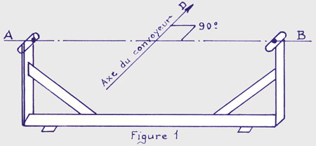
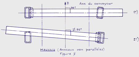
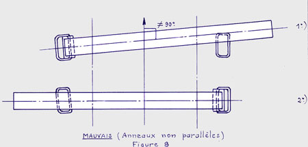
They include two rings used to attach the bearing housings mounted at each end of the roller. The sides of these hooking rings must be well parallel to each other and to the axis of the conveyor.
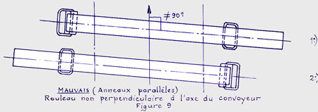
In addition, they will be arranged in such a way that the LIMBEROLLER®, after its installation, is rigorously perpendicular to the axis of the conveyor.
The line A-B represents the longitudinal axis of the roller, which must be perpendicular to the axis D (fig. 1)
Improper assembly is detrimental to the centering of the belt and affects the service life of the disc and cable (fig. 2)

The hooking rings, made of 12 mm round iron, LIMBEROLLER® deform according to the position of the load on the belt. As a result, the belt always remains correctly centered. It is therefore not necessary to provide centering stations.
The mounts can either be supplied by S.A.E.F. or made by the installer.
In the latter case it must be ensured that the distance "Y" between the lateral rollers of the roller and the reinforcements of the support is at least 25 mm for the Type I and 35 mm for the Type II, for avoiding that When the LIMBEROLLER® move, mainly under the loading hoppers, the discs rub and seize against these reinforcements.
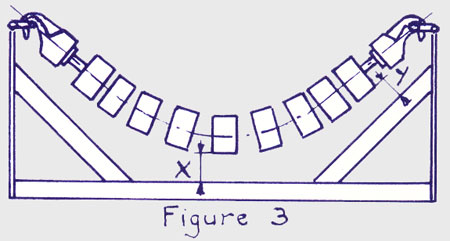
Similarly, the distance "X" between the lower part of the central disc and the upper part of the crossbar of the support must be at least 45 mm, in order to prevent the material accumulating under the roller from wiping the central disc .
On the other hand it is important to ensure that the bearing housings rotate freely on the hooking rings.
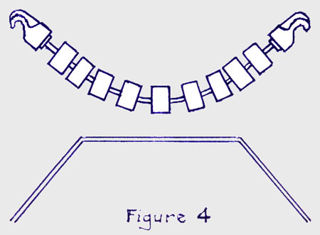
In order to avoid any accumulation of products under the LIMBEROLLER®, it is recommended, as far as possible, to remove the apron between the carrier strand and the return strand or to incline the edges sufficiently so that the products can not accumulate.
If the deck is removed, do not forget to provide a deflector on the lower run before the return drum to eliminate products that may have fallen from the upper run.
SUPPORT VERIFICATION
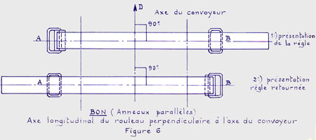
This verification is carried out very simply by means of a special flat ruler, which we can supply on request, and having at one end a heel with a "V" notch.
The ruler is placed on the support of LIMBEROLLER® in such a way that the notch fits on the lower part of one of the hooking rings, the other end then covers the opposite ring (see FIG. 5) .
Perform the same operation by returning the ruler and bringing the notch to the second ring. In both cases, the free end must exactly cover the ring on which it rests.
If the position of the rings is judged to be correct, hold the ruler in either position and check that it is perpendicular to the axis of the conveyor.
The following figures show this method of verification.

|

